Measure the two openings
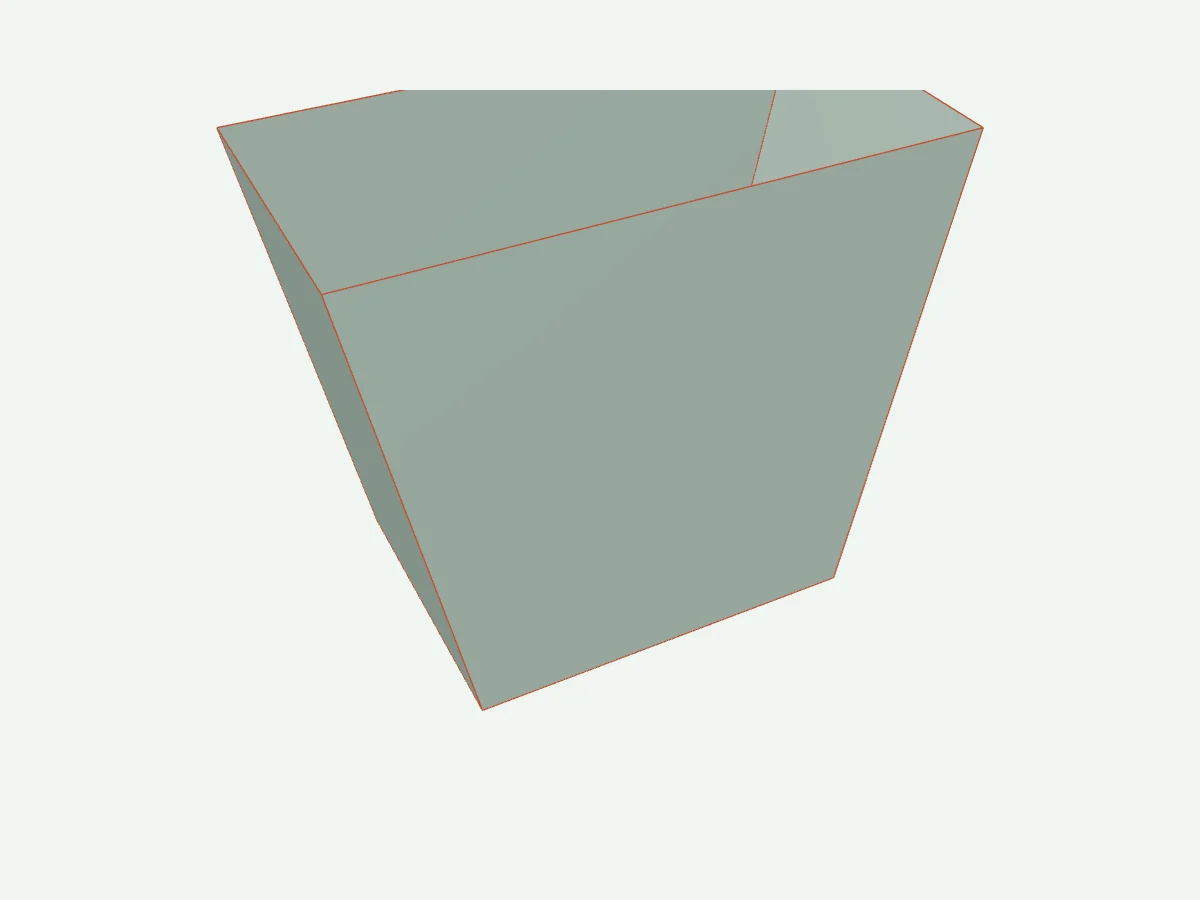
Upper width is shared by both openings. Enter upper length, shared width, lower length and vertical height. The upper length must exceed the lower length. The centered openings give two vertical faces and two opposing sloping faces.
The computed alignment is applied after every calculation, reset and shared-link restore.
How the flat patterns are calculated
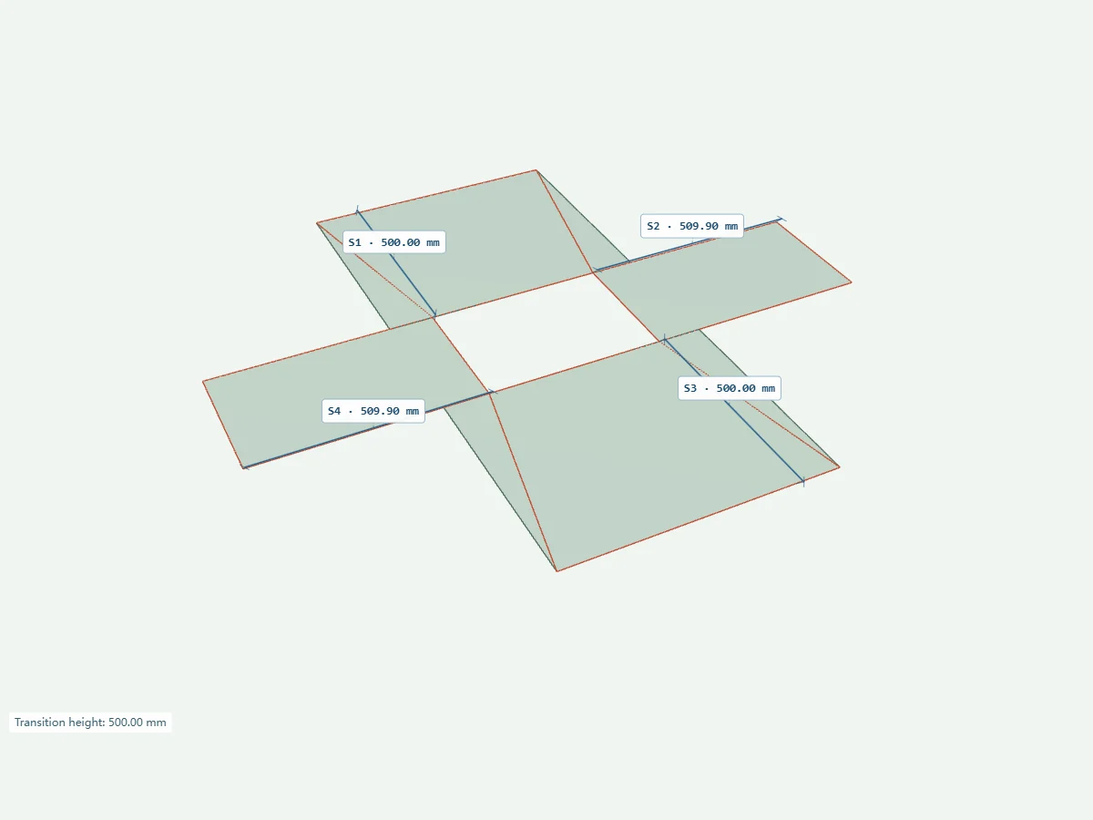
For a centered shape, dx = (upper length − lower length) / 2 and dz = (upper width − lower width) / 2. True face heights are √(H² + dz²) for the length-edge panels and √(H² + dx²) for the width-edge panels. A corner edge is √(H² + dx² + dz²). With offsets, each panel uses its own perpendicular setback and along-edge shift.
Each four-corner panel is unfolded by an isometry: all four edges and both diagonals match the 3D panel. The assembly animation rotates each panel rigidly about a reference edge. It does not interpolate or stretch the sheet.
Default example
600 × 300 mm → 400 × 300 mm · H 500 mm True face height: 500.00 mm / 509.90 mm / 500.00 mm / 509.90 mm.
Fabrication and assembly method
- Inspect the four rectangular panel blanks. These are separate panels, not a continuous tray blank.
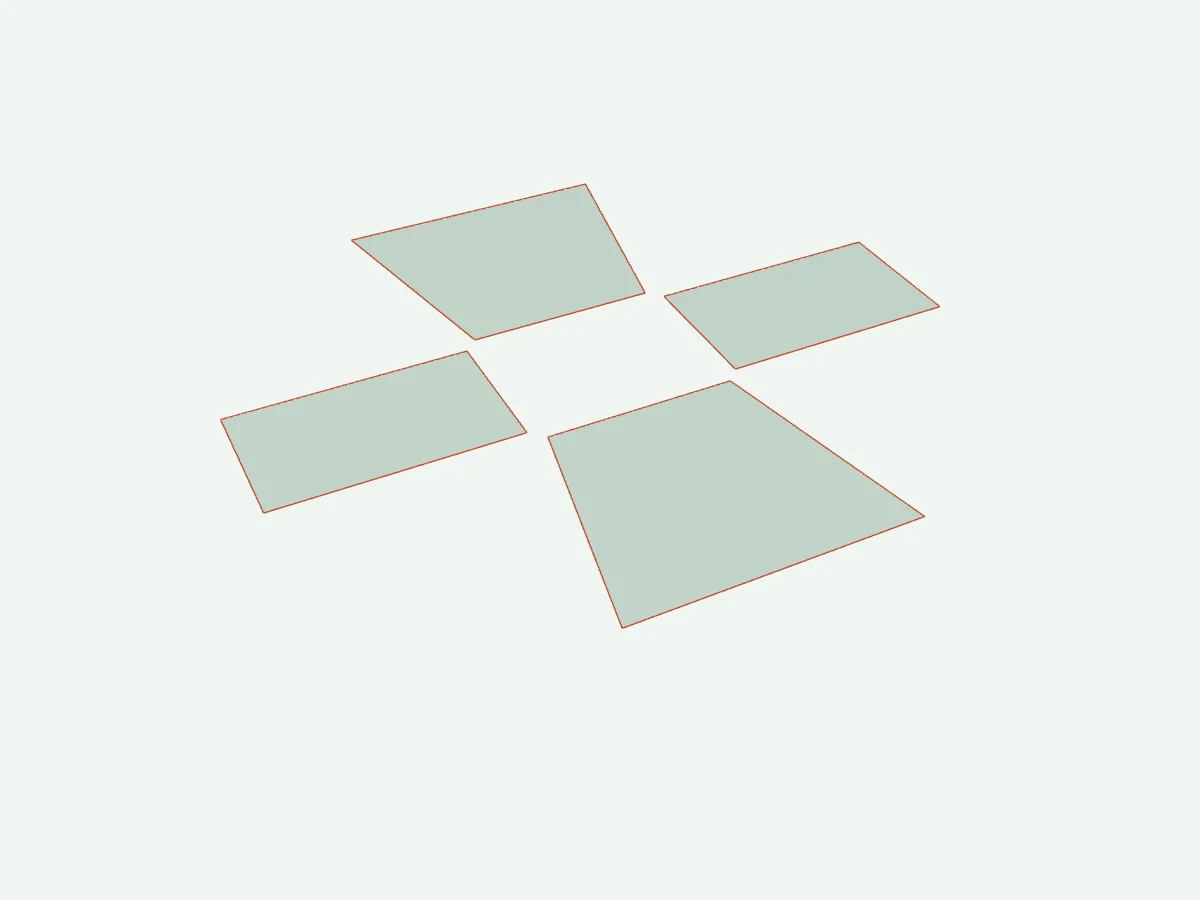
- Mark each true trapezoid outline on its blank. Red lines are the panel cut boundaries.
- Cut the four panels to the marked outlines; the separated panels show their finished boundaries.
- Assemble the panels about their lower reference edges and join the corner seams. These edges locate assembly; they do not imply a retained material hinge.
Ideal sharp, zero-thickness panel geometry. Panel dimensions exclude kerf, bend allowance, seams, overlap tabs, fasteners and the openings cut in the parent tray. The assembly is a separate-panel method; confirm the actual joining detail.
Independent TrayNeo panel-development method. Reference-product correspondence remains under review.
Geometry references
Rectangular transition: face-height equations ↗NPTEL · True-length development ↗
Related calculators
Other rectangular funnel method ↗All numbered methods ↗